SERVO32 Quick Start Guide
Factory Optic's SYNCRO-LINK SERVO32 can control up to 32 lens motors with a single Hand Unit.

Description
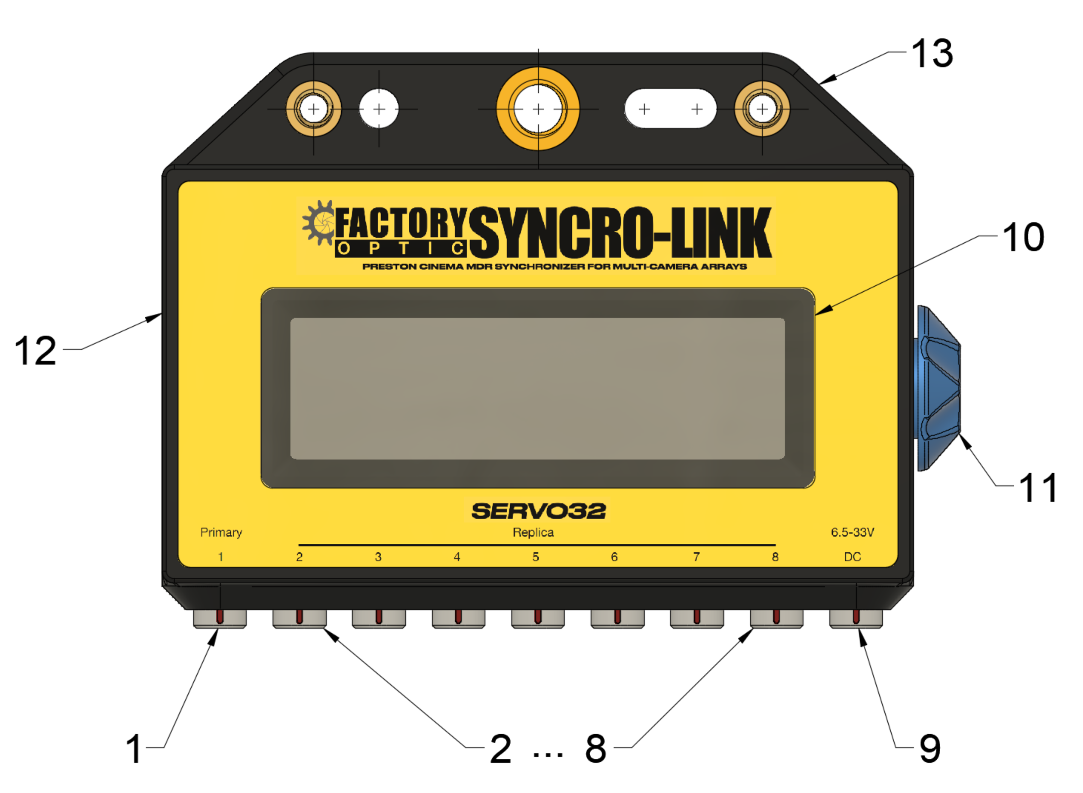
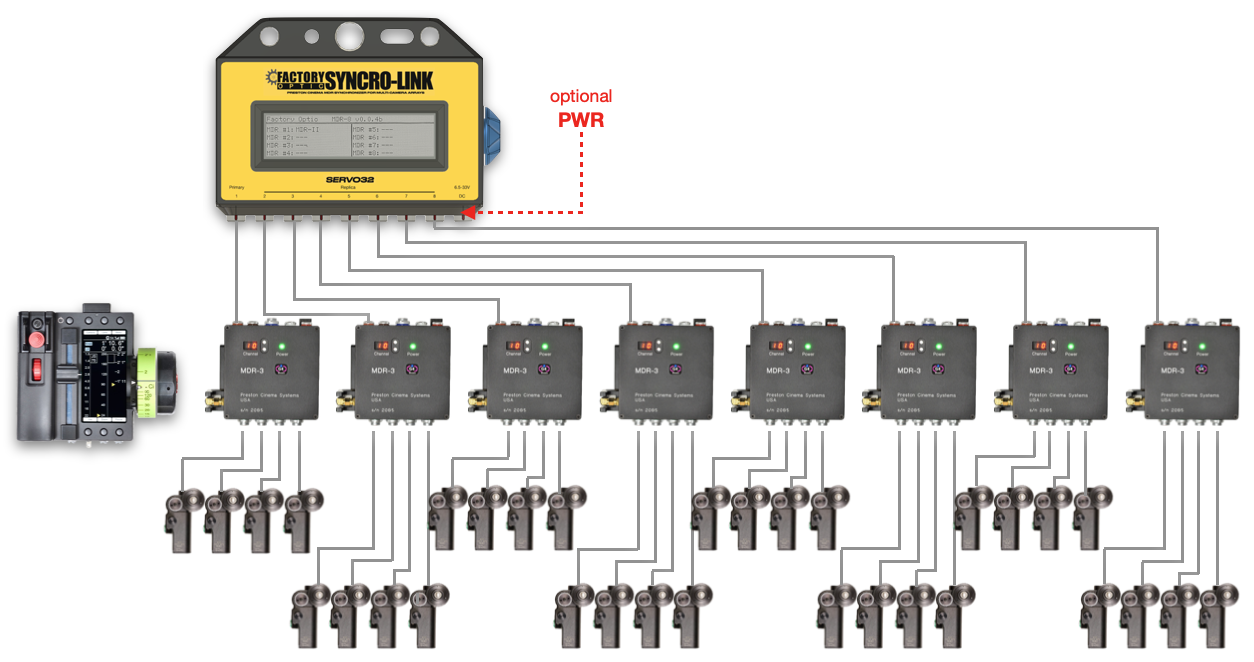
The SERVO32 connects up to 8 MDRs using a single Hand Unit. All MDRs use their serial port to connect to the Primary port (1) and Replica ports (2).
Primary Port MDR
The MDR connected to the Primary port (1) should be linked to the Preston Hand Unit via RF or command cable. The Primary MDR typically provides power to the SERVO32 over the serial cable. When using a primary MDR-2, it is recommended to also provide power on the 2-pin Lemo.
The Primary port is providing position data to the SERVO-32 and the data only flows from the MDR to the SERVO-32.
Note on Selecting Your Primary MDR
Avoid MDR-2 if possible as a Primary, as the serial data update rate is not as fast as the newer MDRs. If you have mixed MDR-3 and MDR-4 in your setup and are only mapping iris it is best to choose the MDR-4 as your primary to make maximum use of your motor ports.
Replica Port MDRs
MDRs can be connected to any of the Replica ports (2-8). Order typically doesn’t matter until mapping is enabled. Replica MDRs will be commanded by the SERVO-32 and should not be connected to any Preston Hand Units.
The motors on the MDRs connected to the Replica ports are normally mapped one-to-one with the motors on the MDR at the Primary port. For example, the iris motor of the Replica ports will be driven by the value of the iris motor of the Primary port. Same with focus, zoom and aux motors.
When using the SERVO32 in mapped mode any Replica motor can be mapped to any Primary motor with a custom mapping table.
Optional Power Port
8-32V DC power can be applied to the 2-pin Lemo (9). This is optional, but recommended when MDR-2 is connected to Primary/Port 1. This power will not leave the SERVO-32 meaning it will never feed power to the MDRs over the serial port.
SERVO32 Display
The SERVO32 Display (10) will provide status of the MDRs connected and show the motor positions.
SERVO32 Rotary Knob
The Rotary Knob (11) is used for changing the display page on the Display.
SERVO32 USB Connection
The USB Micro-B Connector (12) is used for mapping configuration with the SERVO32 console and is not needed for Unmapped mode. It is also used for firmware updates.
SERVO32 Mounting Options

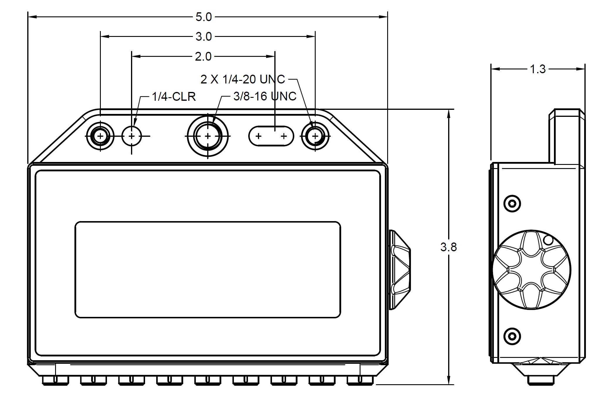
The SERVO32 can be mounted via the following interfaces (13):
- 3/8-16 threaded hole
- 1/4-20 threaded holes at 3" hole-to-hole spacing
- 1/4-20 clearance hole and slot
- Supports 1" hole-center cheese plate (2 inch)
- Supports 9mm hole-center cheese plate (45mm or 54mm)
- Velcro
Wiring Setup

In order to connect the SERVO32 and additional components, use the following connections:
- Preston Serial, ports 1 - 8 of SERVO32
- Connector is Lemo 4-Pin 0B
- Port 1 is the Primary MDR and can provide power to the SERVO32
- Ports 2-8 are the Replica MDRs, no power is provided or taken on this connector
- Supports MDR-2, MDR-3 or MDR-4
Cable Pinout
Be sure to connect all 4 pins. Even though Replica MDRs won’t send power to the SERVO32 the pins are used to detect the presence of the MDR.
| EGG.0B.304 | EGG.0B.304 |
|---|---|
| Pin 1 | Pin 1 |
| Pin 2 | Pin 2 |
| Pin 3 | Pin 3 |
| Pin 4 | Pin 4 |
When connecting DC POWER (optional, recommended when MDR-2 is connected to Primary/Port 1) keep the following in mind:
- Connector is Lemo 2-Pin 0B
- 8-32VDC input @ 4W max
- Input is protected from reverse polarity and has resettable fuse
- Wired to Preston Polarity Standard
| EGG.0B.302 | Signal |
|---|---|
| Pin 1 | Ground |
| Pin 2 | +8~32VDC |
Additional Settings
Click to learn more about the display settings, MDR settings, or Preston compatibility.
Unmapped Mode
The SERVO32 in unmapped mode needs no configuration. Be sure to confirm mapping is disabled.
Here it is ideal to use the same model lenses with identical lens barrels. By using the same model lenses the iris, focus, zoom & aux motor positions at a Replica port will match the motor positions at the Primary port. When using mismatched lenses, the MDR at the Primary port will set the limit of lens motors that are controllable at the Replica ports. For example, we have an MDR-4 at the Primary port and a MDR-3 at the Replica port. The MDR-4 only has Iris and Focus Motor Ports, so only the Iris and Focus Motor Ports on the MDR-3 will be usable, not the Zoom and Aux.
Mapped Mode
Mapping allows seamless integration of any MDR and any lens. For advanced setups, use mapping to achieve barrel-mark accuracy across all lenses. Check out the Mapping Overview.
Customization
SERVO32 can be expanded to support an infinite number of motors, challenge us with your desired modifications and customizations.